Advancing thermoplastic composite primary structure and morphing wings
The HERWINGT project in Clean Aviation seeks to ready technologies — including at least 16 composite demonstrators — for a hybrid-electric regional aircraft with 50% less fuel burn to be launched by 2035.

The Clean Aviation HERWINGT project is developing a novel, ultra-high performance wing for a hybrid-electric regional aircraft, including thermoplastic composites (TPC) and morphing composite wing components, with up to 20 composite demonstrators to be completed by the end of 2026. Source | HERWINGT project, TU Delft and FIDAMC
Part of Clean Aviation’s Green Regional Aircraft program (GRA), the Hybrid Electric Regional Wing Integration Novel Green Technologies (HERWINGT) project aims to develop a novel wing for Clean Aviation’s Hybrid Electric Regional Aircraft (HERA) project, targeting an aircraft with 100 seats, 500-1,000 kilometers of range and entry into service by 2035.
Project goals, technologies, demonstrators
HERWINGT will pursue a wing that helps HERA achieve a 50% reduction in fuel burn/ greenhouse gas emissions compared to a 2020 state-of-the-art aircraft. It will do this through novel, drag-reducing wing configurations, more integrated systems and new material technologies.
The latter rely heavily on composites and target 15% reduced weight and 20% reduced fuel burn at the wing component level. The wing being developed includes a truss-braced configuration, where composite struts extend from the fuselage to support the wing.
Coordinated by Airbus Defense and Space (Airbus D&S, Madrid, Spain), HERWINGT will analyze architectures and perform trade-off studies for a full wing, while building physical demonstrators for a center wing section (pylon-to-pylon):
- Integrated center section wing box structure with the inner propulsion stage including pylon-to-pylon torsion box concept with multi-spar architecture, access panels and integrated fuel vent systems.
- Inner section leading edges with integrated inductive ice protection system plus additional multifunctionality such as erosion, impact and lightning strike protection as well as morphing concepts.
- Inner section flap with multifunctional design and integrated high-lift solutions.
Key processing technologies in HERWINGT include low-cost, highly integrated, out-of-autoclave (OOA) composites:
- Dry fiber placement and liquid resin infusion for integrated multi-spar torsion box.
- In situ consolidation (ISC) thermoplastic composite (TPC) for integrated flap skin and leading edge applications.
- TPC welding and co-consolidation for integration.
- Exploration of bonding technologies that can be certified.
HERWINGT also commits to delivering:
- Digital twins and a life cycle assessment (LCA) of the components,
subsystems and full wing system compatible with the reference aircraft digital framework and requirements. - Roadmap for the full-scale wing demonstration at aircraft level with a first flight.
- Qualification and certification plan for the HERA linked to the proposed activities.
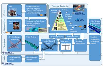
HERWINGT key technologies as presented at AIAA SciTech in January 2025. Source | HERWINGT project overview presented by Airbus Defense & Space
Slated to be completed in 2026, HERWINGT started in January 2023 and has received a 10-month extension to complete the larger demonstrators and testing. It will now end in October 2026 and deliver its new wing design to the HERA project, which is coordinated by Leonardo (Rome, Italy).
TPC leading edge
FIDAMC produced a 1 × 4-meter stiffened upper cover for a wingbox in the OUTCOME project using carbon fiber/PEEK as preparation for its work in HERWINGT. Source | FIDAMC, CW news
ISC TPC structures are being advanced by several HERWINGT partners, including GKN Fokker (Hoogeveen, Netherlands) — see video — and the composites technology center FIDAMC (Getafe, Spain). “We started working with these structures in the Clean Sky 2 project OUTCOME,” explains Isabel Martín Hernando, researcher and technical coordinator of TPC activities at FIDAMC. “Our goal was to demonstrate reduced-weight primary aircraft structures made using automated fiber placement [AFP] layup and ISC. With AFP equipment supplier MTorres [Torres de Elorz, Spain], we developed a complete testing pyramid to demonstrate that the material fulfills the wing’s structural requirements. The finished part was then tested by Airbus D&S, validating the estimated loads calculated in their FEA models. From these test results, we started preparation for the HERWINGT project.
“The idea was to continue using AFP ISC but to increase the geometry complexity,” she continues. “In OUTCOME, we demonstrated an upper wing box skin cover with stiffeners that had a simple curvature. In HERWINGT, we will produce the center wing box leading edge. We have also evolved the process from a gantry machine to a Kawasaki robot, which aids with the more complex structures.” She adds that FIDAMC is working with MTorres on the coordination for a rotational mandrel with the AFP robot, enabling greater flexibility for more complex geometries.
FIDAMC is using a robotic AFP system with a laser divided into four segments to produce an in situ consolidated TPC leading edge demonstrator for HERWINGT. Source | FIDAMC
“We have also changed the AFP heating source,” says Hernando. “We again have a diode laser, but it's divided into four segments which can be controlled separately. We can place up to four 0.5-inch-wide tows, and with this divided laser, we can point to each individual tow. Thus, we can choose to laminate with one, two, three or all of them. This is more versatile for manufacturing the leading edge because at certain areas, such as the leading edge nose, we need to laminate with fewer tows.”
Stiffeners for this leading edge include T-shaped longitudinals and ribs. These begin with stamp-formed components. “For the longitudinal stiffeners, we first stamp two L shapes and then place these with a filler (noodle) in between into a consolidation tool,” explains Hernando. “We then integrate and co-consolidate these during a second heating cycle in an oven. In this way, we will also make T-shaped ribs.”
FIDAMC will produce the TPC leading edge using its AFP with a rotary axis, placing the skin on top of prefabricated TPC stringers and ribs placed into complex tooling. Source | FIDAMC
These stiffeners will then be placed into complex tooling that FIDAMC has developed with HERWINGT partner Aciturri (Miranda de Ebro, Spain). “This tooling will be installed in our rotational mandrel,” she notes, “and the skin will then be laminated on top, co-consolidating the first layer to the stiffeners and afterwards laminating the full skin using AFP ISC. Aciturri is also working on a plasma-based ceramic deposition process to increase erosion resistance.”
The overall idea, says Hernando, is to reduce the weight compared to a metal structure and further advance the ability to use TPC for primary structures. These areconsidered more sustainable due to the ability to use recycled content, as well as co-consolidation and welding to eliminate fasteners, and the further ability to recycle TPC parts at end of life. AFP ISC also avoids autoclave cycles, offering reduced energy consumption during layup and cure.
PEEK, AFP process, LMPAEK for flap demonstrator
For the HERWINGT leading edge demonstrator, FIDAMC is using APC2 PEEK material (Syensqo, Alpharetta, Ga., U.S.). “We developed a large testing pyramid and database on this material during OUTCOME, and that information was used by Airbus D&S to determine the loads and design of this structure,” says Hernando.
In the OUTCOME project, FIDAMC developed an AFP ISC process that used two lasers and two consolidation rollers — one during tape laydown and one in between the roller. “In OUTCOME, we were managing the cooling stage in the material to control the crystallization of the polymer to ensure the mechanical properties,” explains Hernando. “But now we have made further developments after additional demonstrators. We can obtain good crystallization in the material by using self-heated tooling. This also helps to prevent thermal residual stresses and geometrical distortion. So, we now use the segmented laser and a single compaction roller.”
FIDAMC will also use AFP ISC to produce the composite structure for the HERWINGT flap demonstrator. “For this, we will use Toray [Nijverdal, Netherlands] TC1225 prepreg tape, but only in the lower skin and spar for which we are responsible. Aciturri will coordinate the other structures using various technologies.”
TC1225 comprises carbon fiber and LMPAEK polymer from Victrex (Clevelys, U.K.). Hernando notes FIDAMC selected TC1225 with Aciturri. “We had used this lower-melt temperature material during the MFFD project, not directly in the full 8-meter demonstrator, but in a small testing campaign with Aernnova. So, as we had a full testing campaign with APC2, we wanted to extract that same information with LMPAEK in order to allow engineering departments to calculate and prepare these AFP ISC designs for different structures.”
Morphing wing components
Full-scale wind tunnel prototype equipped with a morphing aileron as developed by Polimi. Source | Politecnico de Milano
Another key part of HERWINGT is the development of morphing wing surfaces to increase aerodynamic efficiency. “The idea is to have a wing surface that is able to change shape without classical control surfaces so that the structure — typically the trailing edge and leading edge — are not using separate parts moved by a traditional actuator,” explains Dr. Sergio Ricci, professor of aerospace science and technology at the Politecnico di Milano (Polimi, Milan, Italy). “It is challenging because you have to solve two different problems at the same time: Structures for this part that are able to deform and selecting the optimal shape for aerodynamic performance.
“In HERWINGT, we are developing three main solutions,” he continues. “The first two involve the morphing leading edge and trailing edge with two different applications: flaps and ailerons. The morphing leading edge and trailing edge aileron are being developed by Polimi, while the trailing edge flap is being developed by the aerodynamics group and smart structures group at CIRA.” He is referring to another HERWINGT partner, the Centro Italiano Ricerche Aerospaziali (CIRA, Capua, Italy). The third solution is a morphing strut, being developed by another group, which we will discuss below.
Within HERWINGT, Polimi is developing a morphing aileron for the leading edge and trailing edge made using glass fiber/epoxy, which it has used in many other such demonstrators. Source | HERWINGT project post and Politecnico di Milano
Composites are being used to develop all of these morphing structures. “If you want to do morphing by deforming the structure, you need material with a very high elongation, in some cases with tunable internal stiffness,” says Ricci. “Fiber-reinforced composites are the most flexible solution because you can optimize fiber orientation to get your performance.” Although there are solutions based on carbon fiber-reinforced polymer (CFRP), the team at Polimi decided to use glass fiber-reinforced epoxy. “It depends on how much deformation you need,” he explains. “In the case of the morphing trailing edge flap, you need a very large deformation. An aileron, meanwhile, is not so challenging because you only have to move up and down. Each time you have different requirements, you can select the best material for those.”
So, Polimi chose glass fiber because it enables better elongation than carbon fiber. “But also because we started this type of activity about 10 years ago and all our other demonstrators were based on glass fiber,” says Ricci. “So, we have a lot of knowledge and experience with it and are satisfied with its performance. There are also other issues, such as fatigue. For now, we decided to not complicate the material aspect and stay with what we have validated.”
He points out that the solutions being developed by Polimi in HERWINGT are not based on smart materials, but instead on smart structures. “This means we are using a smart design and normal composite materials. We don’t use piezoelectrics and so on. We are working on the leading edge, which will be combined with the trailing edge produced by CIRA, and then the morphing will be tested in full scale in our large wind tunnel.”
Morphing composite wing struts
The third morphing development in HERWINGT regards the wing struts and is being completed at the Delft University of Technology (TU Delft, Netherlands). It is explained here by two TU Delft researchers: Xavier Carrillo Córcoles, research engineer in aerospace structures and materials and Jurij Sodja, assistant professor of aerospace engineering. The idea is that since the truss-braced wing being considered for the HERA in HERWINGT already has struts, why not use those as well as the traditional control surfaces and have the struts also change shape?
TU Delft is developing morphing struts where composite sections are joined with elastomer sections to enable deflection and twisting for optimized aerodynamics. Source | HERWINGT project
“TU Delft has been working on morphing surfaces for a few years now,” says Córcoles, “including leading edge and trailing edge parts. Our idea is that you can introduce a slot in the bottom skin and then pull or push the bottom skin of the morphing surface [see figure at right] and that will lead to the desired deflection to improve aerodynamic efficiency.
“This was our first concept, and we have now improved this via the Smart X and Smart Alpha versions which were tested in the wind tunnel as proof of concept,” he continues. “For HERWINGT, we are iterating these using composites. We use different modules made from composites connected with elastomeric sections to form a continuous component. You can then actuate differentially to the twist and camber of the airfoil, enabling you to control and optimize its shape according to flight conditions, during climb or cruise, for example.”
Sodja explains why it’s not possible to use a continuous composite skin: “We move the structure mainly using bending deformations. But if you apply this so that one module deflects up and the adjacent one deflects down, it will cause a lot of tensile and shear forces in the structure. Instead, we cut the tail of the skin and replace that with elastomeric material to make it more compliant. We typically use silicone, creating these sections by pouring liquid silicone in the gap, which bonds well with the composite laminate.”
FE modeling for morphing aerostructures being developed by TU Delft, showing the three main loading cases. Source | Fig. 16, “Design of a smart morphing wing using integrated and distributed trailing edge camber” by Jurij Sodja, et al.
The morphing strut will most likely use glass fiber-reinforced epoxy, notes Sodja. “The glass fiber laminate can give better performance than other materials as long as the structural requirements are not too high. For example, because it is more compliant, the glass fiber laminate can significantly reduce the actuation loads, resulting in lighter actuators and therefore less weight penalty for such morphing concepts.”
For HERWINGT, TU Delft will test its morphing strut demonstrators to assess shape changes and resulting aerodynamic drag as well as the limits for these morphing mechanisms.
Digital twins
Advancing the use of digital twins is a key objective for both the HERA and HERWINGT projects. “Digital twins are frameworks conceived to compile all the information about the product related to the whole life cycle process,” explains Miriam Agúndez Manzano, structural design engineer at Airbus and part of the wing structural design team in HERWINGT. “This includes manufacturing, assembly and scheduled maintenance. As such, the digital twin must be fed from every stakeholder involved in the development and in-service processes.
“In composite parts, digital twins have special relevance in the design-manufacturing stage where these digital models are generated and integrated,” she adds, noting they include not only the part geometry, but also the fiber orientation and rosettes (reference axis) for the plies, as well as the surface protection, part weight and interchangeability, etc. “The resulting ‘as built’ model will be then monitored in service through sensors to evaluate the condition of the structure in real time.
“In practical terms, the core element of the digital twin is essentially a large database,” says Manzano. “It contains the inputs of all the disciplines — including, stress, fatigue, design, manufacturing, maintainability, etc. — involved in the development of the part, and is prepared to include the information corresponding to the future steps of the life cycle. The digital twin also contains a set of algorithms to predict the eventual evolution of failure modes in order to adapt the maintenance plan of the structure to its real status.
“For the HERWINGT project, considering the digital twin technology has been really useful and more productive in the demonstrators’ development at the design level, because this information must be shared between partners,” concludes Manzano. “Using digital twins allows us to have one single ‘source of truth’ for the different steps of the development in which all the information needed is readily available.”
Related Content
Plant tour: Collins Aerospace, Riverside, Calif., U.S. and Almere, Netherlands
Composite Tier 1’s long history, acquisition of stamped parts pioneer Dutch Thermoplastic Components, advances roadmap for growth in thermoplastic composite parts.
Read MoreJEC World 2024 highlights: Thermoplastic composites, CMC and novel processes
CW senior technical editor Ginger Gardiner discusses some of the developments and demonstrators shown at the industry’s largest composites exhibition and conference.
Read MoreComposites manufacturing for general aviation aircraft
General aviation, certified and experimental, has increasingly embraced composites over the decades, a path further driven by leveraged innovation in materials and processes and the evolving AAM market.
Read MoreThe potential for thermoplastic composite nacelles
Collins Aerospace draws on global team, decades of experience to demonstrate large, curved AFP and welded structures for the next generation of aircraft.
Read MoreRead Next
Composites end markets: Aviation and advanced air mobility (2025)
Despite persistent supply chain issues, markets were set for healthy growth before Trump policies and tariffs, yet long-term trends favor composites in new platforms. Meanwhile, the advanced air mobility shakes out and moves forward.
Read MoreIIAMS wing box road map to certification
Airbus DS uses Clean Sky demonstrators as part of broad strategy to ready next-gen aircraft technology for flight.
Read MorePlant tour: Daher Shap’in TechCenter and composites production plant, Saint-Aignan-de-Grandlieu, France
Co-located R&D and production advance OOA thermosets, thermoplastics, welding, recycling and digital technologies for faster processing and certification of lighter, more sustainable composites.
Read More


